Our standard operating modules (also referred to as “display modules” or simply “modules”) make it easy to equip existing or newly-developed devices with an ergonomic, graphical user interface.
A color TFT LCD in combination with a resistive or capacitive touch glass lets the device operator interact with the application intuitively. Our modules can be controlled from almost any hardware. Even less powerful 8-bit microcontrollers are sufficient.
Control of the module by the application
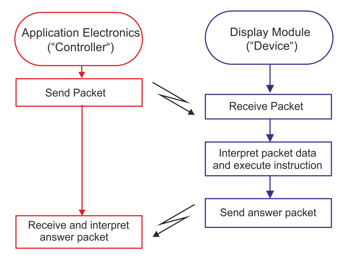
This is how the control basically works:
- The application's electronics tell the module what it wants (e.g. display a variable).
- The operating module executes this request and sends a response.
This is why, in the context of communication, we refer to
- the application electronics as the “controller” – like a customer, it sets the requirements and controls the entire application –
- and the display module as the “device”, which is dependent on the information from the controller and executes its instructions.
Schematically, this looks as follows:
Simple design of the user interface with the GUI‑Designer
To minimize the development effort required on the client side to run an attractive user interface, we have developed a tool called the GUI‑Designer. This tool allows the user interface to be designed graphically. The client then simply sends the relevant data for the application’s variables to the display module, where it is automatically displayed and can also be set and modified by the user.
The GUI‑Designer allows the user interface to be designed without any programming, thereby achieving a logical separation of design and pure functionality. This enables a division of labor, reducing the workload on software developers. As a result, development times and costs are reduced.
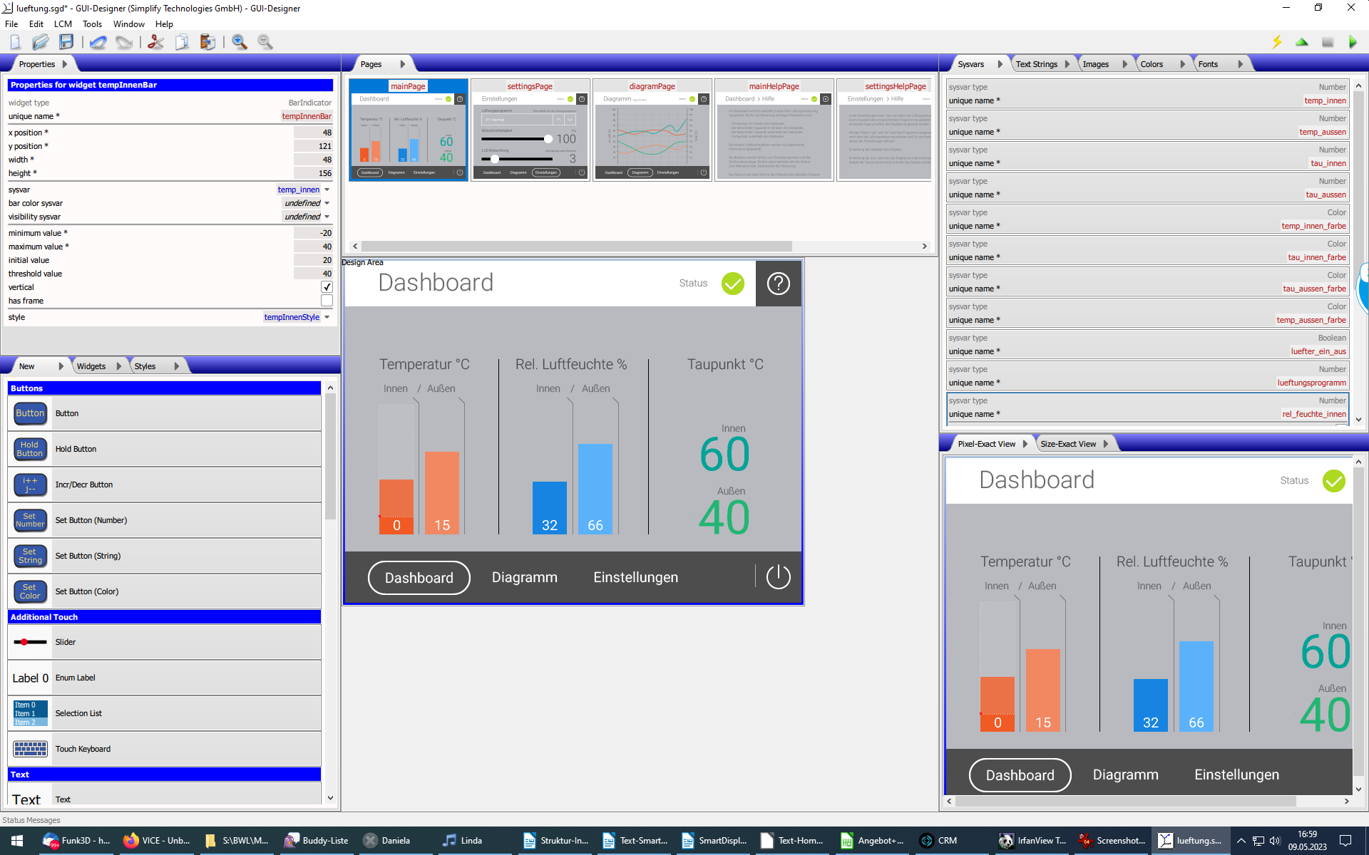
You can find the numerous features of the GUI‑Designer, detailed information, and instructions here:
GUI‑Designer
The objects created with the GUI‑Designer are, in addition to design elements, primarily representations of application variables (“system variables”). These are defined with the GUI‑Designer so that it is sufficient later for their values to be transmitted or read by the application electronics.
Therefore, communication between the application electronics and the display module requires only a few functions that serve to transmit the values of the system variables.
For these communication functions, which are required in the application electronics, we provide a ready-made library (“GUI-Master-LIB”) in ANSI-C, making implementation on the application electronics side straightforward.
Overall, using the GUI‑Designer is the preferred method for creating an attractive user interface with minimal effort and bringing it to life in an application. The use of system variables, their separate definition, and the design of their representation in the GUI‑Designer is the central underlying concept here.
Interaction via graphics commands: Direct control of the GUI‑Interpreter
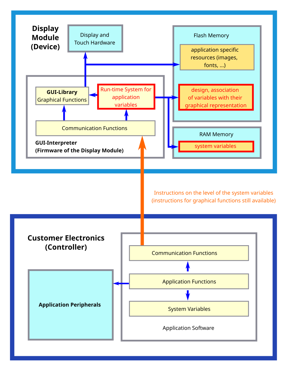
The firmware in the display module is called the “GUI‑Interpreter”. Its main function is to receive commands from the “controller” and execute them on the display module. If you wish to implement special functions, such as custom types of graphic elements, the numerous graphic functions in the GUI‑Interpreter are directly available. They can also be used independently of the functions of the “system variable” concept used with the GUI‑Designer.
Calling graphic functions directly was the original approach used to implement complete applications before the GUI‑Designer was available. It is therefore possible to use the system variables and the GUI‑Designer while also utilizing the direct graphics functions of the GUI‑Interpreter.
The overall relationships are schematically illustrated in the following figure:
 zurück